MR603b Top MR603b Top
- Overview:
-
MR603b is a 2.4GHz DSM2/DSMX receiver which includes one integrated 3A reversable controller for brushed motors (ESC) plus 10 auxiliary outputs (4xF, 6xP) for lighting, sound trigger, couplers, etc. It can be used with any Spektrum DSM2/DSMX compatible transmitter; this includes all of the Micron model rail transmitters or a stick model aircraft type transmitter. MR603b is 38x18x10mm and weighs 3.6g without leads. The voltage range is 5V to 20v and the 3A motor current rating makes it suitable Gauges 0 and 1 plus 16mm narrow gauge. MR603b is available as board-only for you to add wiring or with a range of pre-wired leads / connectors. The standard output configuration is described on the Outputs tab. If the wiring or configuration options do not meet your needs, please contact us to discuss your requirements. An enormous range of programming features are provide to enable you to customise the operation of MR603b to suit your model. See MR6xx Programming for full details or the user manual for brief information. Access to programming is either via a stick type transmitter or one of the Micron model rail transmitters. A stand-alone programmer with web interface is in development.
- Specification:
-
|
|---|
| Size: | 38 x 18 x 10mm |
| Weight: | 3.6g without leads |
| Protocol: | Spektrum DSM2/DSMX |
| Voltage: | 5V - 20V |
| Motor Current: | 3A max continuous |
| P outputs: | 6 (P1..P6), 0V when off, 3.3V when on, max 20mA |
| F switches: | 4 (F1..F4 or A..D) open when off, closed to negative when on |
- Documents:
-
When wiring options are selected, these colours will be used: | P1 | orange | | P2 | turquoise | | A/F1 | blue | | B/F2 | green | | C/F3 | pink |
- Outputs & Configuration:
-
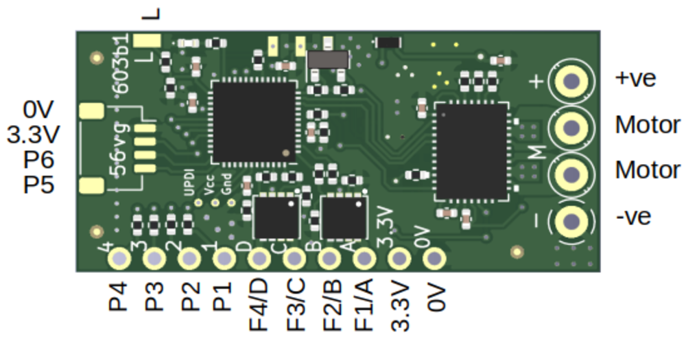
The MR603b has 1 x H, 6 x P and 4 x F outputs. H: MR603b is intended for surface vehicles which require forward and reverse motor control. For brushed motors this is achieved with an H-Bridge - the H outputs. H outputs have 256 step resolution in both directions (512 total). They control speed with pulse width modulation (PWM) which, by default, is set to its fastest (quietest) 16kHz setting. Each H output can handle up to 3A current. The main constraint with current is heat in the receiver. Higher currents may be possible if heat sinks are added or the PWM frequency is reduced. MR603b has one integrated ESC (H1). How the outputs are used has to be set with programming. Receivers are provided 'pre-programmed'. The default settings are shown on the instructions pages for each variant. P: 'P' outputs are 'pads' with 'logic' type outputs. Pads are simply solder points for controlling external things. Logic outputs are either on or off (also known as high/low and 3.3v/0v in voltage terms). The action can be inverted so 'On' can mean 0v or 3.5v. P outputs are used to provide servo signals direct to the white/yellow lead on a servo. P outputs may also be used to drive LEDs and need a resistor to limit current to no more than 20mA. If a P output is connected to another system (e.g. sound card) with an open-circuit voltage > 3.3V, a series resistor is required to ensure the 'pull-up' current is less than 50uA. A 4k7 ohms resistor is suitable when connecting to a MyLocoSound trigger input. A F output does not need the resistor as it is a switch to battery negative when on. P outputs can not be connected to a Mtroniks trigger input as the required current is too high, F outputs must be used instead. F: 'F' outputs are 'buffered' P outputs capable of controlling up to 2A. The buffer is a FET (Field Effect Transistor) which provides a path to ground (0v) when on and is floating (disconnected) when off. Technically they are called 'open drain' (the equivalent with a transistor which is more widely known is called 'open collector'). The MR603b main board provides 4 x 'F' outputs, labelled A, B, C and D. When programming, the F outputs are numbered 7 though 10. F outputs are often used to control sound cards and lights that require more than 20mA. If an installation requires more than 4 F outputs, a P can be converted to an F using one or more FET Buffers. The pre-loaded configurations are shown below. Unless otherwise specified when the receiver was ordered, config 1 is enabled by default. The other loaded configurations can be selected using a power-on configuration change (aka 'paper-clip change') or `by programming. The throttle type can be toggled between Centre-Off and Low-Off using a power-on configuration change.
| Port |
1: Centre-off throttle |
2: MyLocoSound triggers on A-D (Tx22) |
3: MyLocoSound triggers on A-D (Tx20) |
4: Tx with 3-way toggle on ch2 & ch4 |
| H1 |
Centre-Off ch1 |
Centre-Off ch1 |
Centre-Off ch1 |
Low-Off ch1, dir ch3 |
| P1 |
Front Light on H1 (LED2) |
Front Light on H1 (LED2) |
Front Light on H1 (LED2) |
Momentary on ch2, high 0V |
| P2 |
Rear Light on H1 |
Rear Light on H1 |
Rear Light on H1 |
Momentary on ch2, low 0V |
| P3 |
Momentary on ch3, low 3.3V |
Momentary on ch3, low 3.3V |
Momentary on ch3, low 3.3V |
Momentary on ch4, high 0V |
| P4 |
Momentary on ch3, high 3.3V |
Momentary on ch3, high 3.3V |
Momentary on ch3, high 3.3V |
Momentary on ch4, low 0V |
| P5 |
Momentary on ch5, low 3.3V |
Momentary on ch5, low 3.3V |
Momentary on ch5, low 3.3V |
Momentary on ch5, low 3.3V |
| P6 |
Momentary on ch5, low 0V |
Momentary on ch5, low 0V |
Momentary on ch5, low 0V |
Momentary on ch5, low 0V |
| F1/A/P7 |
Front Light on H1 |
Momentary on ch3, high closed |
Momentary on ch2, low closed |
Front Light on H1 (LED2) |
| F2/B/P8 |
Rear Light on H1 |
Momentary on ch3, low closed |
Momentary on ch4, low closed |
Rear Light on H1 |
| F3/C/P9 |
Momentary on ch5, low closed |
Momentary on ch5, low closed |
Momentary on ch5, low closed |
Momentary on ch5, low closed |
| F4/D/P10 |
Latch on ch5, start open, toggle low |
Latch on ch5, start open, toggle low |
Latch on ch5, start open, toggle low |
Latch on ch5, start open, toggle low |
| LED2 |
P1 | P1 | P1 | F1 |
| Selecta |
Enabled |
Enabled |
Enabled |
Disabled |
| LVC |
Enabled |
Enabled |
Enabled |
Enabled |
| Sleep time |
1 hour |
1 hour |
1 hour |
1 hour |
| Cruise |
Enabled |
Enabled |
Enabled |
Enabled |
Other configurations are available to special order or you can configure yourself by programming.
- Low Voltage Cutoff:
-
The default receiver setting is for the Low Voltage Cutoff (LVC) threshold to be determined from the voltage seen on initialisation - basically, the receiver firmware makes a 'guess' at the battery type. The algorithm used for this calculation means that a 9V Alkaline or NIMH battery can often be interpreted as an almost discharged 3S LiPo. The solution is to either disable LVC, or set it to the correct value for your battery; this is done by programming the receiver. Instructions for programming receivers using your transmitter are at the bottom of the information leaflet that came with the transmitter. The receiver programming steps for LVC are: disable LVC: 7 2 1
set LVC: 7 2 3 units tenths e.g. to set the LVC to 6.5V, the programming steps are: 7 2 3 6 5
- More Images:
-
To Be Completed.
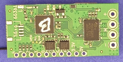
The receiver is normally supplied as a bare board, with wiring options as specified in the menus below. The MR603b is fitted with a 100mm extended aerial - mount the receiver so that the last 30mm of the aerial can 'see' the transmitter. If you want the receiver protected against accidental contact with metal parts, please select the 'heatshrink' option.
Price: from £45.00
|